Detailed Drainage Design Calculation for Rain Catchment Areas
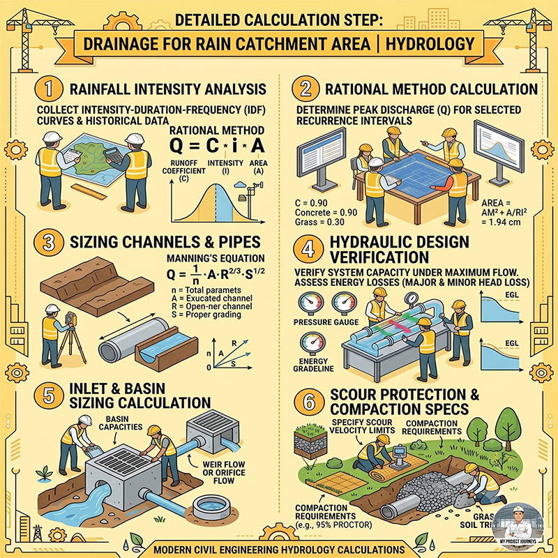
Proper drainage design is essential for preventing flooding, protecting infrastructure, and ensuring long-term site performance. The infographic illustrates a systematic hydrological approach used by civil engineers to calculate and design effective stormwater drainage systems.
1. Rainfall Intensity Analysis
The first step is collecting historical rainfall records and Intensity-Duration-Frequency (IDF) data. Engineers analyze rainfall characteristics to determine the design storm intensity for a selected return period. This information forms the foundation for estimating peak runoff from the catchment area.
2. Peak Runoff Calculation Using the Rational Method
The Rational Method is widely used for small and medium-sized drainage catchments:
Q = C × I × A
Where:
- Q = Peak discharge (m³/s)
- C = Runoff coefficient
- I = Rainfall intensity
- A = Catchment area
The runoff coefficient varies depending on surface conditions such as concrete, asphalt, grass, or soil. Higher impervious surfaces generate greater runoff volumes.
3. Channel and Pipe Sizing
Once peak discharge is known, drainage channels and pipelines are sized using Manning’s Equation:
Q = (1/n) × A × R^(2/3) × S^(1/2)
This calculation ensures that channels and pipes can safely convey stormwater without overtopping or excessive flow velocity.
4. Hydraulic Design Verification
Hydraulic analysis verifies system performance under maximum design flow conditions. Engineers evaluate pressure losses, hydraulic grade lines (HGL), energy grade lines (EGL), and potential bottlenecks to ensure reliable drainage operation.
5. Inlet and Basin Sizing
Catch basins, manholes, and drainage inlets must be designed to capture runoff efficiently. Capacity calculations often incorporate weir flow and orifice flow principles to prevent localized flooding and improve stormwater collection efficiency.
6. Scour Protection and Compaction Requirements
The final stage focuses on protecting drainage structures from erosion and scour. Proper soil compaction, riprap installation, and velocity control measures help maintain system stability and extend service life.
Conclusion
A successful drainage design combines hydrologic analysis, hydraulic calculations, and sound engineering practices. By following these six essential steps, engineers can develop efficient stormwater management systems that reduce flood risk, protect infrastructure, and ensure sustainable site development.
Leave a Reply